|
|
|
Kategorie
|
|
Informacje
|
|
Polecamy
|
|
|
 |
|
|
Dla tego produktu nie napisano jeszcze recenzji!
 ;
Schematy są ale można wysilić się i zrobić kolorowy skan i o większej rozdzielczości. Wtedy schematy płytek będą czytelniejsze. Całość super jako wartość merytoryczna. Wszystkie dane potrzebne do podłączenia różnego rodzajów urządzeń takich gramofon, CD itd.
 ;
Szybko, sprawnie i tanio. Serwis godny polecenia. Będę polecał innym
;
Ogólnie jest OK, z wyjątkiem obrazu płyty głównej, który jest miejscami mało czytelny, ale można sobie poradzić.
;
Dokładna dokumentacja, pomogła w szybkiej naprawie telewizora. Dziękuję!
;
jedyne do czego mogę mieć zastrzeżenie to jakość zdjęć zawartych w przesłanej instrukcji serwisowej ponieważ są fatalnej jakości, praktycznie nieczytelne. tak poza tym jestem zadowolony to jest to czego szukałem.
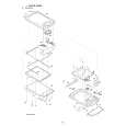
5. DISASSEBLY AND ASSEMBLY PROCEDURES
For disassembly of the ZQ-800, perform the following procedures. For assembly, reverse the disassembly procedures.
2 5 8 8 6
A
1 13
16 15 14 4 14 9 7 3 3
A
12 12 10 11
12
5-1. LOWER CABINET 4 AND UPPER CABINET 5 DISASSEMBLY
1. Remove the stylus 1. 2. Slide the battery replacement switch to the �REPLACE BATTERIES� side, and remove the battery compartment lid. 3. Remove two alkaline batteries. 4. Remove two screws 2. Note: Do not apply an excessive force when removing the screws. 5. Remove two screws 3. Note: Do not apply an excessive force when removing the screws. 6. Separate the lower cabinet 4 from the upper cabinet 5. [Note for separating the lower cabinet] � First, disengage all the pawls around the cabinet. � The Main PWB unit 6 and the LCD unit 7 are connected with FPC. When separating the lower cabinet 4, remove the lower cabinet 4 from the jack cover side of the PC-LINK so that an excessive load may not be applied to the FPC connector of the Main PCB unit 6 and the FPC solder section of the LCD unit 7. 7. Remove the FPC from the FPC connector of the Main PWB unit 6. [Note for the FPC connector] � When handling the FPC connector, be careful not to apply a reverse load to the connector lock section.
About 120 C FPC insertion side FPC connector PWB
Release the lock smoothly
Lock plate FPC insertion side
Do not press the Lock plate unnecessarily in the reverse direction. FPC connector PWB
ZQ-800 DISASSEBLY AND ASSEMBLY PROCEDURES
� 13 �
|
|
|
> |
|