|
|
|
Kategorie
|
|
Informacje
|
|
Polecamy
|
|
|
 |
|
|
Dla tego produktu nie napisano jeszcze recenzji!
 ;
Schematy są ale można wysilić się i zrobić kolorowy skan i o większej rozdzielczości. Wtedy schematy płytek będą czytelniejsze. Całość super jako wartość merytoryczna. Wszystkie dane potrzebne do podłączenia różnego rodzajów urządzeń takich gramofon, CD itd.
 ;
Szybko, sprawnie i tanio. Serwis godny polecenia. Będę polecał innym
;
Ogólnie jest OK, z wyjątkiem obrazu płyty głównej, który jest miejscami mało czytelny, ale można sobie poradzić.
;
Dokładna dokumentacja, pomogła w szybkiej naprawie telewizora. Dziękuję!
;
jedyne do czego mogę mieć zastrzeżenie to jakość zdjęć zawartych w przesłanej instrukcji serwisowej ponieważ są fatalnej jakości, praktycznie nieczytelne. tak poza tym jestem zadowolony to jest to czego szukałem.
Service Modes, Error Codes, and Fault Finding
5.8.2 Start-up Sequence
COLD HOT
EM6E AB
5.
EN 37
EHT-INFO
When you suspect the �ARC� protection, look for bad solder joints and smell. By interrupting resistor 3497, this protection is disabled (special attention needed!). When you suspect the �BRIDGECOIL� protection, which can also be due to a too wide picture amplitude, shorten G and S of the E/W MOSFET 7480. This will disable the protection. You will now have minimal horizontal amplitude. Re-align the horizontal amplitude in the SAM menu and remove the G/S short of TS7480.
2
8V 2 I C BUS 1
5 START/STOP 17/39 HOP 29 START/STOP OUT
5VCON RESET 106 8VCON 105 OTC 99 POR 104 8V STANDBY low 7131/41 closed high 7131/41 open 3 7131 7141 5V
CUTOFF (from CRT panel)
5.8.5
Main Supply The simplest way is, to replace the components of the Main
220 VAC
STBY SUPPLY
Supply with repair kit 3122 785 90550. More detailed way:
MAIN SUPPLY
Vbat
SUP-ENABLE
1. Replace FET 7504 and zener 6505. 2. Disconnect the SSP panel. 3. Short B and E of TS7529, in order to put the Main Supply in �on�-mode (TS7529 is blocking then). Caution: To prevent that R3403 and TS7443 will be damaged, first disable the HW-protection of the deflection circuit. Therefore short circuit C2642 on the LSP (diagram A4). 4. Attach a load of 500 � to V_BAT capacitor C2515 (the supply can not work without a minimum load). 5. Use a variac, and slowly increase the V_MAINS. Measure over sensing resistors R3514//15, if a nice sawtooth voltage becomes available. 6. Also measure the V_BAT. This may never exceed +141 V. If it does, there is something wrong in the feedback circuitry (e.g. regulator 7506). Note: Be careful when measuring on the gate of FET TS7504. This circuitry is very high ohmic and can easily be damaged (first connect ground to measuring equipment, than measure the gate). 5.8.6 Standby Supply The simplest way is to replace the components of the Standby Supply with repair kit 3122 785 90530. 5.8.7 Line Deflection The simplest way is to replace the components of the Line Deflection circuitry with repair kit: 3122 785 90330 Caution: item 3400 used in this chassis is different from the part supplied in the kit. See partlist for correct value and ordercode. 5.8.8 Frame Deflection Caution: When the Frame Deflection circuitry is suspected, one must be careful. Because there is a DC-voltage on the frame deflection, the beam current could damage the CRT neck, leading to a defective CRT. To prevent this from happening, you must: Interrupt the resistors 3403 and 3404 on the CRT panel (diagram F1), in order to remove the �filament� voltage from the tube (no beam current, so no chance of destroying the CRT). Interrupt resistor 3403 on the LSP (diagram A4) to disable the �SUP-ENABLE� line. Measure with a multi-meter, or better with an oscilloscope, the functionality of the Frame stage. After you have found the cause, exchange the defective component (e.g. TDA8177), and re-solder the interrupted resistors.
+11D POR 7445
LINE DEFL. (BRIDGECOIL -PROT) (ARC-PROT) PROTSENSING FRAME DEFL (NON-VFB)
CL16532044_023.eps 140501
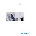
Figure 5-4 Start-up circuitry The start up sequence differs from other sets (e.g. MG-sets or EM2E-sets, but is same as in EM3E-set): 1. When the set is switched �on�, the 5 and 8 V lines (�+5V_CON� and �+8V_CON�) of the standby power supply are activated. 2. After the OTC senses them, the µP will address the HOP via the I2C-bus, to start the drive [1]. 3. Via the �SUP-ENABLE� signal, the Main Supply is switched �on� and will deliver the V_BAT to the Line deflection stage [2]. 4. EHT generation is now started. 5. The OTC will un-blank the picture. 6. When you switch �off� the set, this is done in a controlled way via the POR signal [3]. Note: Standby is not directly achieved via the Standby line of the microprocessor, but indirectly via the HOP circuitry. 5.8.3 ComPair This chassis does not have an IR transmitting LED (as in MGsets). Therefore, a �Service� (ComPair) connector is implemented at the rear side of the set, which is directly accessible (as in A10-, EM2E-, EM3E and EM5E-sets). In addition to this, there is also a blinking LED procedure to show the contents of the error buffer. When you use ComPair, you have the possibility to activate a �stepwise start-up� mode. With this mode, you can initiate the start-up sequence step by step. This also means that in certain steps, some protections are not activated. This is sometimes very convenient during repair. 5.8.4 Protections Activating SDM via the �service pads� will overrule the processor-controlled protections, but not the hardware protections. This means, that the A/D-input protections (5 and 8 V) and the I2C �not-acknowledging� info of the feature box (FBX) and of the Tuner are overruled. Caution: When doing this, the service technician must know what he is doing, as it could lead to damaging the set. The �ARC�- and/or �BRIDGECOIL� protection are hardly ever triggered, however:
|
|
|
> |
|