|
|
|
Kategorie
|
|
Informacje
|
|
Polecamy
|
|
|
 |
|
|
Dla tego produktu nie napisano jeszcze recenzji!
 ;
jedyne do czego mogę mieć zastrzeżenie to jakość zdjęć zawartych w przesłanej instrukcji serwisowej ponieważ są fatalnej jakości, praktycznie nieczytelne. tak poza tym jestem zadowolony to jest to czego szukałem.
 ;
Wszystko w porządku.
Instrukcja czytelna i kompletna.
Dziękuję.
all right!
thank you.
;
Bardzo dobra instrukcja. Zawiera wszystko co potrzeba, polecam!
;
Instrukcja jest OK. Schematy czytelne, opisane niektóre procedury.
;
Instrukcja bardzo czytelna. zawiera co potrzeba. Polecam
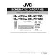
4.2 Mechanism compatibility adjustment Note: � Although compatibility adjustment is very important, it is not necessary to perform this as part of the normal servicing work. It will be required when you have replaced the A/C head, drum assembly or any part of the tape transport system. � To prevent damaging the alignment tape in the compatibility adjustment, prepare a cassette tape (for self-recording/playback), perform a test on it by transporting it and making sure that the tape is not bent by the tape transport mechanisms such as in the guide rollers.(See Fig.4-2b.) 4.2.1 Tension pole position Note: � This adjustment must be performed every time the tension band is replaced.
Signal Mode (A) � Back tension cassette gauge [PUJ48076-2] (B1) � PB (B2) � Eject end � Adjust pin [Mechansim assembly]
4.2.2 FM waveform linearity
Signal (A1) � Alignment tape(SP, stairstep, PAL) [MHPE] (A2) � Alignment tape(LP, stairstep, PAL) [MHPE-L] (UA Model) (A1) � Alignment tape(SP, stairstep, PAL) [MHP] (A2) � Alignment tape(EP, stairstep, PAL) [MHP-L] (UB, UM Model) (B) � PB (C) � Oscilloscope (D) � TP106 (PB. FM) (E) � TP111 (D. FF) (F) � Guide roller [Mechanism assembly] (G) � Flat V. PB FM waveform (H) � Roller driver [PTU94002]
Mode Equipment Measuring point External trigger Adjustment part Specified value Adjustment tool
(1) Play back the alignment tape (A1). (2) Apply the external trigger signal to D.FF (E), to observe the V.PB FM waveform at the measuring point (D). (3) Set the VCR to the manual tracking mode. (4) Make sure that there is no significant level drop of the V.PB FM waveform caused by the tracking operation, with its generally parallel and linear variation ensured. Perform the following adjustments when required. (See Fig. 4-2c.) (5) Reduce the V.PB FM waveform by the tracking operation. If a drop in level is found on the left side, turn the guide roller of the pole base assembly (supply side) with the roller driver to make the V.PB FM waveform linear. If a drop in level is on the right side, likewise turn the guide roller of the pole base assembly (take-up side) with the roller driver to make it linear. (See Fig. 4-2c.) (6) Make sure that the V.PB FM waveform varies in parallel and linearly with the tracking operation again. When required, perform fine-adjustment of the guide roller of the pole base assembly (supply or take-up side). (7) Unload the cassette tape once, play back the alignment tape (A1) again and confirm the V.PB FM waveform. (8) After adjustment, confirm that the tape wrinkling does not occur at the roller upper or lower limits. (See Fig. 4-2b.) [Perform adjustment step (9) only for the models equipped with SP mode and EP (or LP) mode.] [Perform adjustment step (9) only for the models equipped with SP mode and EP (or LP) mode.] (9) Repeat steps (1) to (8) by using the alignment tape (A2).
Improper Proper
Adjustment part (F) Specified value (G)
� 25 - 51 gf·cm (2.45 - 5 x 10⁻³ Nm)
(1) Play back the back tension cassette gauge (A). (2) Check that the indicated value on the left side gauge is within the specified value (G). (3) If the indicated value is not within the specified value (G), perform the adjustment in a following procedure.(See Fig.4-2a.) a) Remove the top frame, cassette holder and side frames (L/R) all together. (Refer to the SERVICE MANUAL No.86700 [MECHANISM ASSEMBLY].) b) Rotate the loading motor gear to move the control plate so that the triangular stamping to the left of the "P"stamping is aligned with the stamping (a) on the main deck. This positioning is mode (B1). c) Adjust by turning the adjustment pin so that the tip of the tension arm is aligned with the stamping (b) on the main deck. d) Rotate the reel disk (S) by about one turn clockwise and make sure that the round hole of the adjustment pin is located in the "OK" range. If it is outside this range, restart the adjustment from the beginning. After completion of the adjustment, rotate the loading gear motor to return it to the mode (B2) position.
TENSION ARM
(a) GUIDE ROLLER
CONTROL PLATE Stamping(a)
Stamping(b) OK
(b) GUIDE POLE
Fig.4-2b
NG
ADJUST PIN
Fig.4-2a
(No.YD007)1-11
 $4.99 HR-J4020UA JVC
Schematy Zestaw schematów dla tego urządzenia. Plik PDF zawierający schematy będzie dostarczony na Twó…
|
|
|
> |
|