|
Dla tego produktu nie napisano jeszcze recenzji!
 ;
Dokładna dokumentacja, pomogła w szybkiej naprawie telewizora. Dziękuję!
 ;
jedyne do czego mogę mieć zastrzeżenie to jakość zdjęć zawartych w przesłanej instrukcji serwisowej ponieważ są fatalnej jakości, praktycznie nieczytelne. tak poza tym jestem zadowolony to jest to czego szukałem.
;
Wszystko w porządku.
Instrukcja czytelna i kompletna.
Dziękuję.
all right!
thank you.
;
Bardzo dobra instrukcja. Zawiera wszystko co potrzeba, polecam!
;
Instrukcja jest OK. Schematy czytelne, opisane niektóre procedury.
29 January 1998
MASTER FEED
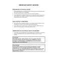
5. REPLACEMENT AND ADJUSTMENT
5.1 MASTER FEED
5.1.1 THERMAL HEAD VOLTAGE ADJUSTMENT
VR1
CN503
C228R500.WMF
Purpose:
To maintain the quality of masters and to extend the life of the thermal head.
Adjustment Standard: There are two steps. 1) The output voltage for the thermal head from the power supply unit must be 22.5 volts (r 0.5). 2) The output from the DC/DC converter board is different from one thermal head to another. Refer to the voltage value (X) on the thermal head decal. The output should be between "X-0.1" and "X" volts. NOTE: This adjustment is always required when the thermal head or power supply unit is replaced. 1. Turn off the main switch and remove the paper exit cover plate (4 screws). 2. Disconnect connector CN503 of the power supply unit. 3. Turn on the main switch, and access the SP mode and select output check mode (SP131) No. 41. 4. Press the Print Start key to apply thermal head voltage continuously (60 seconds). 5. Check the voltage between CN503-15 and CN503-12. If the voltage is not 22.5 volts (r 0.5), turn VR1 on the power supply board to adjust the voltage.
Replacement Adjustment
5-1
|