Service Schematics
Introduction
IMPORTANT: This document is intended for use by authorized NOKIA service centers only.
�Service Schematics� was created with focus on customer care. The purpose of this document is to provide further technical repair information for NOKIA mobile phones on Level 3/4 service activities. It contains additional information such as e.g. �Component finder�, �Frequency band table� or �Antenna switch table�. The �Signal overview� page gives a good and fast overview about the most important signals and voltages on board. Saving process time and improving the repair quality is the aim of this document. It is to be used additionally to the service manual and other training or service information such as Service Bulletins.
nokia
6670 7610
RH-67 RH-51
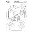
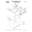
Exploded view and component disposal
All measurements were made using following equipment:
Phoenix version A16 2004.32.6.62 Fluke PM 3380A/B Advantest R3162 with an analog probe Rhode & Schwarz CMU 200 Fluke 73 Series II
While every endeavour has been made to ensure the accuracy of this document, some errors may exist. If the reader finds any errors, NOKIA should be notified in writing. Please send E-Mail to: [email protected]
Table of Contents
Front Page Baseband connection overview System connector, USB, Charger UEME, SIM, Zocus, Mic, Ear, IHF Speaker UPP, Flash, MMC, Camera Bluetooth UI, Vibra RF-part Signal overview Component finder