|
|
|
Kategorie
|
|
Informacje
|
|
Polecamy
|
|
|
 |
|
|
Dla tego produktu nie napisano jeszcze recenzji!
 ;
Dokładna dokumentacja, pomogła w szybkiej naprawie telewizora. Dziękuję!
 ;
jedyne do czego mogę mieć zastrzeżenie to jakość zdjęć zawartych w przesłanej instrukcji serwisowej ponieważ są fatalnej jakości, praktycznie nieczytelne. tak poza tym jestem zadowolony to jest to czego szukałem.
;
Wszystko w porządku.
Instrukcja czytelna i kompletna.
Dziękuję.
all right!
thank you.
;
Bardzo dobra instrukcja. Zawiera wszystko co potrzeba, polecam!
;
Instrukcja jest OK. Schematy czytelne, opisane niektóre procedury.
XM-PX55BU/MX-PX55SL XM-PX55RD
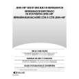
Removing the feed motor (See Fig.12)
1. Peel off the part h of the flexible wire on the underside of the feed motor. 2. Unsolder the solder joint i connecting the flexible wire to the feed motor. 3. Peel off the part j of the flexible wire. 4. Remove the two screws J attaching the feed motor on the upper side of the chassis assembly. ATTENTION: When reassembling, reattach the flexible wire with an adhesive tape and solder the appropriate part.
Chassis
Feed motor
j
J
i
h
Fig.12
Removing the switchi board assembly (See Fig.12)
1. Remove the switchi board assembly attached to the side of the chassis assembly with the double-sided tape. 2. When reassembling, reattach the switchi board assembly with an adhesive tape as before.
Switchi board assembly
Fig.13
1-8
|
|
|
> |
|